TECHNICAL SOLUTION
Name of solutionCombined heat and power emergency system - based on wood gasifier
Category of solution
> Electricity production [LINK] > Heat [LINK] > Energy storage [LINK] |
PDF version to download
Related Energy School
> Renewable energy |
Short introThe Combined Heat and Power Emergency System (noted as System further on) is a junkyard derived solution to provide emergency power & heating from local wood resources in time where sunshine, wind or hydro are unavailable, like in winter months for emergency situation (short time manual operation). The System gains its energy from the gasification of the quantity of firewood typically burnt in a home furnace for heating. The System can be combined with solar, wind, hydro or biogas energy and enhanced by automation for longer term (days-weeks) usage. The System provides scaleable water heating, space heating and electricity generation in quantities suitable for domestic use from cabin size to small family home for basic living needs. |
Complexity and cost of building and operatingThe system is a DIY build. There are various aspects that will require handyman level welding skills, mechanical skills (drilling holes, connecting nuts and bolts), measuring and basic electrical wiring skills. Cost and time depends on the scale of the build, the cost of outsourced skills if needed and whether recycled junkyard parts or new parts are utilized. The base system for an adequately skilled handyman using junkyard parts costs around 500 EUR for parts, with a build time around 80 hours. Operation skills required depends upon the level of automation electronics employed. A minimal system will require hands on involvement and learned skills, whereas enhanced system with full automation requires little more than the ability to light a typical home wood furnace. |
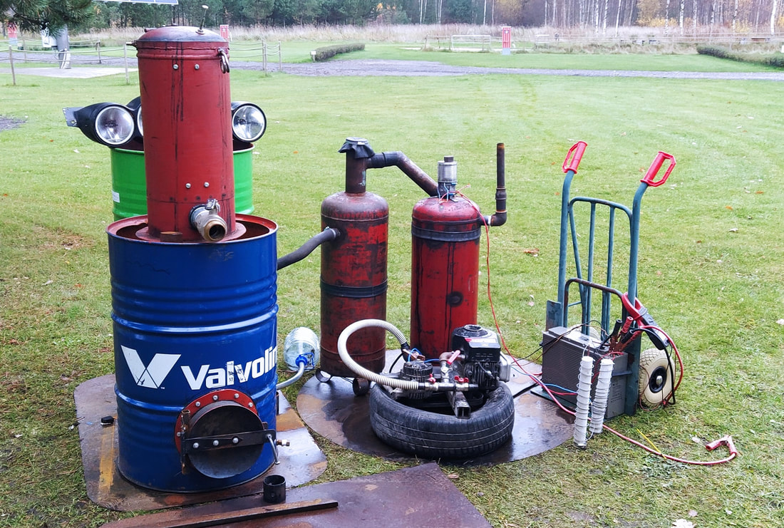
Description of the solutionThe solution given here describes the base unit with no automation and utilizing commonly available junkyard parts and some hardware store parts. The system can operate either from wood gas, which can be replaced for warmer months with biogas, and enhanced further with ability to utilize solar, wind and hydro power instead. For the wood gasifier the modified U.S. Federal Emergency Management Agency (FEMA) design is used. Wood gasifier provides heat for water and space heating and provides the wood gas required to fuel a modified lawn mower engine, which runs the electric power generation by modified car alternator. This engine is started manually either by pull cord, electric starter or electric drill. Once the engine starts, the operator switches the alternator on to charge a 24 V DC battery bank. The battery bank can utilize scavenged car/truck batteries that may no longer be adequate for vehicle starting, but are still quite capable for home power storage. The system provides around 5 kWh of battery storable power from 5 hours burn time, which is a typical burn time for home furnaces in winter. An inverter can be attached to the batteries to convert 12/24V DC to 230V AC suitable to power home appliances/tools. A 5kW inverter would be adequate for most homes, however lower capacity power inverters will work too, so long as care is taken to appliances power ratings and simultaneous appliance usage. The battery storage amount will provide for basic living needs if used with care. Expansion for more stored power is as simple as adding duplicate generator units or higher rated engine and multiple alternators and additional batteries. Technical illustrations
|
|
Skills, tools & materials requiredTools
Stick/MMA welder, Electric drill (drill press preferable), disk grinder, basic hand tools, multimeter. Skills Handyman level welding, accurate measuring, basic electrical skills, able to use a multimeter, know positive from negative and able to wire 12-24 V DC connections. Materials For the generator: - lawn mower or stationary engine, 4.5 hp or more, with pull or electric start. Electric start is more convenient, but are more expensive/harder to find as junk. - 1 x car or truck alternator, 12V or 24 V, 100 A or better, preferably functional. - 1 x larger micro V belt pulley from the crank shaft of a car engine - 1 x micro V belt around 800 mm circumference - 2 m x 40 mm square 4 mm wall steel box tubing - Old 14” car tire without rim - 1x trampoline spring - 1 x 20mm plumbing T joint - 200 mm of 20 mm rubber fuel line, with hose clamps to suit - 200 mm of 8 mm rubber fuel line, with 1 hose clamp to suit - 2 x 20mm water taps, 90 degree rotation, switch arm type - 1 x 20mm water tap, 90 degree rotation, lever arm type - 1 x pit bike pod air filter - begged/borrowed standard BBQ LPG/propane bottle, hose and regulator for initial test - 1 x adjustable alternator regulator if using AGM, Gel or Lithium-ion batteries (https://www.240turbo.com/AdjustableVoltage.html) - Automotive jumper/booster cables and heavy and light insulated wires - 2 x 200 A battery isolation switches - 10 m of 2 mm dia steel tie wire - 1m of 45 mm diameter plastic drain pipe - 1.5 m of 8 mm re-bar - 2 kg plaster of paris (quick-setting gypsum plaster) For wood gasifier & water heater: - 1 x 220 l steel oil drum, drum with sealable lid preferable - 5 x Russian type propane bottles 300 mm dia x 700 mm or 9 x EU propane 9 kg bottles 300 mm dia - 500 mm standard 150 mm dia steel chimney tube - 1 x 1 quart (=liter) conical stainless steel kitchen measuring cup, 150 mm dia at top - 1 x 0.5 quart stainless steel kitchen measuring cup, 50 mm dia at bottom - Top 1⁄2 of standard oxy bottle or CO2 or Argon...(Not Acetylene), 400 mm x 230 mm diameter or tube 200 mm diameter - Stainless steel kitchen sieve 200 mm dia at top - 20kg fire place mortar/concrete - 3 m fire door fire-proof sealing rope - 2 x fence/door hinges - 30 x M8 nuts, bolts & washers - 12 x M8 30mm long nuts - 3 x M8 50mm hex bolts - 1m M8 threaded stainless rod - 8 x M10 nuts, bolt, washers - 2m x 8mm dia steel rod - 500mm x 20mm square tube - 100mm x 50mm angle iron - 100mm x 40mm dia threaded pipe, threaded bend, Cap - 300mm x 20mm dia threaded pipe - Copper brake paste - Exhaust manifold sealant - 1m chicken wire - Wheel barrow inner tube - Heavy duty motorcycle inner tube - Rock wool insulation to wrap oil drum, 100 mm thickness – - Anti freeze coolant for 300 l suitable for use with ferrous metals - Pipe plus fittings to connect to home heating via home furnace. For gas cooler/water pre-heater/tar return: - 1 x 220 l steel oil drum, drum with sealable lid preferable - 400mm x 150mm dia chimney flue - 1m x 40 mm dia steel exhaust tube - 10m 20 mm dia standard galvanized water pipe - 1 x 40mm dia threaded pipe elbow - 1m 40mm dia radiator hose - Rock wool insulation to wrap oil drum, 100mm thickness – Anti freeze coolant for 300 l suitable for use with ferrous metals - Pipe plus fittings to connect to home heating via home furnace. For gas filters & blower - 2 x Russian type propane bottles 300 mm dia x 700 mm or 4 x EU propane 9 kg bottles 300mm - 1.2m x ~90mm dia steel pipe - 500mm x 50mm dia steel pipe - 12V blower (automotive heater type) - 2 x 100mm dia hose clamps - 3 x standard size metal buckets (295mm dia at top) - 6m 30mm width door jam foam tape - 2m chicken wire or fine wire mesh - 2 x 150mm x 20mm dia threaded pipe, - 2 x 20mm threaded elbows, - 2 x 20mm threaded caps - 2 x 16” bicycle inner tubes |
Other preconditions or requirementsThis is a dangerous project. In operation there is real possibility of gas explosion, shrapnel injury, electric shock, burns, gas poisoning, CO suffocation, fire. In other words a great project for careful risk takers. Do take care, get help where you are unsure.
Take careful attention to air tightness of everything in the gasifier, air leaks here can cause an explosive air/gas mixture. This is an invisible danger, you wont know until it goes “boom”. Also choking the gasifier to shut it down will produce dangerous CO, which is a very real suffocation hazard gas, if the system is in an enclosed space or indoors. Best to install the gasifier where there is good ventilation to outdoors and each time run the gasifier until it has consumed all the fuel wood. Be aware also that over time cracks and decay of metal parts from extreme heat, vibration and fatigue can cause air leaks, shorts, gas leaks, general meltdown, so make sure to install in such a place where consequences will be minimal and to check everything thoroughly and regularly. Take extreme care when first cutting propane & Oxy cylinders. |

|
Conclusions and errors to avoidUse open top/sealable 220l drums as these allow a degree of flexibility allowing easier installation of the cores. Use thick, good quality copper wires for all the heavy duty wiring jobs from battery to alternators. Take care around the micro V belt and do fit a guard. It is surprisingly easy and quite the tear bringer getting fingers pulled around between the belt and pulley. Make sure to use stainless steel where specified & as thick walled as you able to find. These specified places experience very high temperatures, normal steel will erode within weeks. The design eliminates the need for stainless welding other than the attachment of lugs to secure the stainless components in place. |
Cost & Life cycle analysisThe System will increase wood consumption by about 10% compared to the typical wood fired home furnace. This ‘cost’ in fire wood will be insignificant when compared to the fueling and disturbance of the typical diesel/petrol generator usually employed in winter months. The batteries will fail after time. The more batteries the longer they last, however it is a large expense to build a large battery bank. This is the unspoken of dark side to off-grid energy, the energy is “free”, but the storage is definitely not, and often its cost can exceed grid supply energy costs. It is a hard truth, but one that has to be faced and factored into your off-grid homes running costs. In this System build we suggest to buy comparatively cheap truck batteries or reuse discarded car/truck batteries and accept that they will fail every year or 2, depending on real usage and conditions. The on-going cost will still be less, when factored against the eliminated diesel/petrol. The lawn mower engine will fail eventually, good oil changed regularly will help extend its life. They are built quite poorly, however the thing that lets most of them down in their role as lawn mowers is the carburetor. This is removed for this solution, so you will find most old discarded lawn mowers quite suitable for this job and very cheap. Eventually the engine will run to its death by the failure of the plastic cam, big end failure, broken aluminum conrod or the unlined aluminum barrel worn to slop. The car alternators will last many years. The brushes will wear out, the slip rings wear away and bearing eventually get noisy. These can be replaced/repaired or just replace the whole thing with another junkyard special. It is difficult to say how long these components will last, it really depends upon the condition when found, care of build and maintenance and how you use your electricity in your home. The gasifier will fail around the pyrolysis zone, the grate and wood feed tube will need to be built from thick stainless steel to increase lifespan. Expect to replace iron or steel versions of these every few months of operations, stainless steel every year or 2. |
|
Step by step guidelines for building the solutionIf using AGM, Gel or Lithium-Ion batteries order from online an external adjustable alternator regulator (https://www.240turbo.com/AdjustableVoltage.html).
The 20 mm T joint fittings and 20 mm water taps are common parts at typical hardware stores. Next go shopping at your nearest scrap metal merchant or recycling center. Try your luck finding a 24 V, >100A alternator. A scrap alternator will cost less than 10 EUR, often it is only worn brushes or failed regulator, which can be repaired. Alternatively buy a used alternator from an auto breakers, it will cost around 60 EUR, but should be at least in working order. Get an alternator fitted with a micro V belt pulley. The old single V belts & pulleys are inefficient & make for harder work when trying to start the generator. Look for a lawnmower whose chassis has rusted through or wheels have fallen off, chances are this is the reason it has been discarded and the engine is probably fine. Try to get one with a functioning pull cord and make sure the engine turns freely with some resistance from the internal compression. Steel from the scrap merchant will cost around 50 cents per kilo, compared to 20 EUR for the 2 meter length plus cutting fee from a steel merchant. While at the scrap yard check out their battery pile. Using a multimeter check the Voltages, if it reads above 12 V then there’s a reasonable chance it may work OK for a little bit of storage power for a while. A visit to your hardware or auto store for some heavy duty car jumper cables, get something rated at 200 A or more. Get 5 m of smaller 10 A rated wire also, red and black and a few other colors too. Get some large screw terminal blocks too. Buy some long bolts, probably 8 mm or 10 mm to fit through the holes on your fantastic new junk alternator. Pick up the stainless steel chimney tube and fire door heat proof sealing rope. The battery isolators can be got from automotive parts/accessory shops. Full parts list given above. Lawn mower test run
Try to start your junk lawn mower. First check the blade is secure underneath, important: remove the spark plug lead before meddling with the blade, it may fire and reduce your finger count. When you tip the lawn mower on its side, tip it towards the exhaust side so oil doesn't run into the air filter and carburetor and create more work for you. Check the oil, remove, clean and replace the spark plug and refit the spark plug cap. Don't worry about cleaning the carburetor or putting petrol in the tank, you only need to find out if it runs, you’ll throwing the carburetor away in the next step. Remove the air filter cover and poor about 5 table spoons of gasoline onto the filter or down the carburetor throat. Promptly try to start the engine. If the pull cord is broken or missing you can remove the cover and fit a socket onto the flywheel bolt and spin it with a drill. If it fires up and runs for a few seconds and makes no unusual knocking then you have a winner, if not starts then check for spark. Other fixable problems can be stuck or sooted up valves. Failing that you have a dud, probably best go visit the scrap man again. Lawn mower strip
Remove the petrol tank and carburetor from the lawn mower engine. Remove the blade, make sure to remove the spark plug cap first. Next remove the engine from the lawn mower. Drain the oil, flush out with diesel, drain it thoroughly and refill with the good oil. If the pull start is non functional then either repair or cut the pull starter off. The engine can be easily started using a drill with socket onto the flywheel nut. Generator Mechanical Make a T section using heavy walled 40mm box section tubing as shown. Mount points will vary according to the engine & alternator used. A trampoline spring can be used to provide tension for the belt. Use micro V belt pulleys as these are far more efficient than the old single V pulleys/belts. Use a large ~130mm diameter micro V pulley taken from either the crank or power steering pump from a car. Using a new(square edged) 1.2mm cutoff disk, rest the disk flat to the lawnmower blade flange & cut smooth any protrusions. Drill & tap M8 threads into the flange for securing the pulley. Take care with centering but doing this by eye is good enough. Use the picture as a guide line. Long bolts loosely slid through holes in the chassis lock the chassis to holes drilled into a 14” car tire. The tire greatly reduces noise and vibration. Re-drill the ignition coil mount holes to retard the timing by about 5degrees. This is necessary, otherwise the engine will not start & will fire against your efforts to start. Make sure to refit the engine cowling as this forces air blown by the flywheel to the engine cylinder & head to provide necessary cooling. Engine gas connections
Construct a gas mixer as pictured using 20mm Taps & fittings. The Large handled tap is for the throttle, the smaller taps for gas & air mixture. Not shown is a pod air filter which would normally sit at the air intake. Drill a 7mm hole into the bottom side edge of the pod filter body. Press in the rubber fuel line so it enters only a few millimeters. This is to be connected to the engine oil breather pipe to assist engine operation & reduce engine emissions. 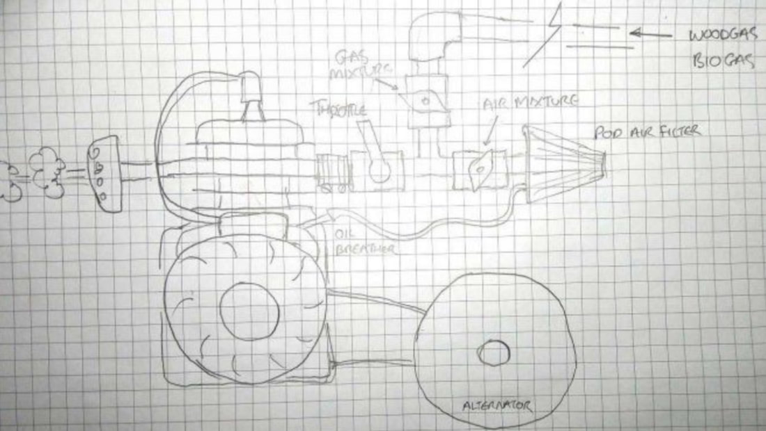
Building the load reduction resistors
These are only needed if your engine is under rated compared to your alternator. A 3.5 hp engine will stall trying to charge flat batteries at full rate from a 100Amp alternator. The load reduction resistors can be switched into circuit by opening its shorting isolation switch. When the initial high rate of charge reduces, the resistor can be shorted again using the isolation switch allowing the alternator to charge at a higher rate. Cut the 1 m x 50 mm plastic tube in half and split down both sides. Tape back together & tape one end closed using masking tape. Cut 2 pieces of re-bar to 600 mm. Insert the re-bar into the open end of each tube & force it through the center of the tape at the other ends, push through so 50 mm protrudes. Mix the plaster of paris & fill both tubes. Align the re-bar to the center and hold in place with tape. Let dry over a day or 2. Once dry remove the tape & plastic tube. Wrap 2.5 m of the steel tie wire around each plaster rod. Connect together in series using screw terminals with the plastic removed. Beware, these resistors will get very hot in operation. Support each resistor off the ground using supports on the re-bar at each end. Engine wiring
Connect the adjustable regulator to the brush block of the alternator if required. Remove the clamps from the booster cables. Connect about 200 mm of the heavy red booster cable wire to the + terminal of the alternator, connect the other end to a battery isolation switch mounted somewhere within easy access near the air and gas intake valves. Label this switch as ‘load reduction’. Connect a 400 mm length of the red wire from the junction of the 1 st red wire to 1 side of your load reduction resistor situated on the ground to protect it from engine vibration. Cut another 400 mm length of the red wire and connect it from the unused resistor wire to the other side of the battery isolator. Cut a 100 mm length of red wire and connect it from the same terminal on the battery isolator to the 2nd isolator switch. Label this isolator as ’isolator’. Connect the remaining red wire from the remaining terminal on the 2nd isolator to the other end to the + terminal on a 12 V battery. Label this terminal as ‘+24 V’. Turn the isolator to its OFF position. Cut a 200 mm length of the heavy black booster wire and connect it to the – terminal of the 1 st battery. Connect its other end to the + terminal of the 2nd 12 V battery. Connect the remaining black wire from the – terminal of the 2nd battery. Label this battery connection as ‘Ground’ and connect it to the body of the alternator. 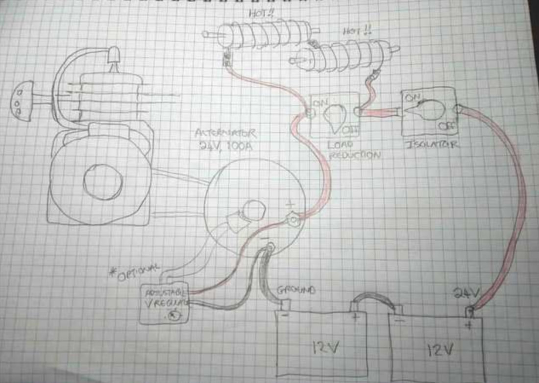
Wood gas unit design
The method described here is similar in operation to the FEMA stratified wood gas unit version. However the following modifications have been made: - Updated with present day commonly available junk/hardware parts - Designed to scavenge the previously wasted heat and put it to use for home heating. -The blower bypasses the filter during startup to reduce filter clogging. It also blows the woodgas through to the engine to eliminate prolonged cranking. -No speed controller is required for the blower. - Scaled to suit small engines from 4 hp to 30 hp - Preheats and dries the fuel wood prior to entering the combustion zone, steam can escape through condensation on the lid and draining to the exterior. - Condensates the vaporized tar products in the wood gas and feeds them back to the pyrolysis zone for re-combustion. - The combustion zone is lined with refractory concrete to retain high temperatures for pyrolysis. - A large entry is included to ease the lighting process, ash removal, grate and reduction cone inspection/replacement. - The entire inner core is unboltable to ease the rebuild process - The stainless steel fire tube and reduction cone are removable by bolts, minimal stainless welding for attachment lugs only. - Heat is contained within thicker walled propane cylinders rather than the prior thin walls of the 220 l drum - Wood gas temperature is water cooled prior to exiting the gasifier. Wood gas gasifier unit construction
The materials are all commonly available however there will be variances depending upon what materials you can find. This drawing above shows the usage of two Russian type propane cylinders. These can be substituted with four standard EU 9 kg propane cylinders by cutting away unwanted curves and welding together. Take great care when cutting propane or oxy cylinders. The oxy acetylene bottle has a very nice taper at the top which when inverted is very suitable as a reduction zone leading to the fire tube. It has very thick walls which allows a nice seal to be made between it and the fire tube. The fire tube is simply a piece of standard chimney flue tube. The tapered end should be trimmed to make a tight fit to the stainless 1 quart (=liter) conical kitchen measuring cup. A smaller 0.5 quart conical measuring cup is riveted to the bottom of the bigger cup. Together they make a very suitable cone to reduce the fire tube diameter down to the smaller required diameter. Cut the cone at a point which gives the correct diameter to match the expected power draw of your engine as follows: 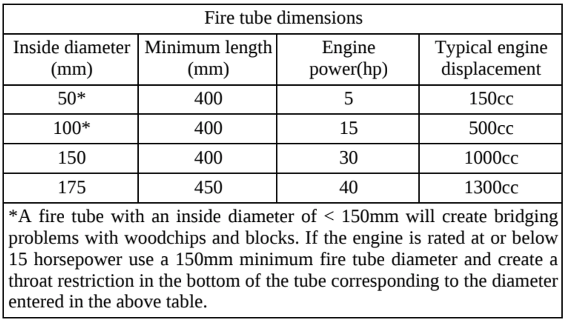
Wood Gasifier Diagram
The cold coolant is force fed from the home heating circulation pump. Entering at the bottom of the gasifier, heated coolant exiting at the top. Coolant should be suitable for ferrous metals. General The instructions that follow are meant as a guideline. They can be followed to the letter using the same materials or sections can be built to suit the materials or skills available to you. Some welding jobs can be substituted by nuts & bolts or riveting. The most essential things are the dimensions of the fire tube so greater detail is given for its construction. The other critical point is to make sure there are no air leaks after the hopper. If the heating aspect is not required then all sections & attachments related can be omitted. Dimensions depend upon the materials you have available so measurements where not noted should be made relatively as described. Use thread tape on threaded pipe fittings to both seal & prevent corrosion seizing the fittings together. Deburr all cuts. Grind off all paint, rust, galv around weld points before assembly. Prime/paint with rust preventing paint all surfaces that may be exposed to constant condensation. Gasifier Core Construction
The Gasifier core consists of a fuel wood hopper with lid & shaker, reduction zone fire tube, gas chamber & access port. Fire tube & reduction zones. This section is the most critical to proper function! This section reduces the area of the fuel wood entering from the hopper. The reduction zones are the tapered sections, the fire tube the straight section. The dimensions are critical to successful gasification, see table 1. For durability materials should be either stainless steal or thick steel/iron. Stainless steel is preferable as it can utilize thinner wall thickness allowing faster start up & give far superior longevity compared to steel or iron. Sustained temperatures of around 900C will be experienced along the lower half of the fire tube. The reduction zone section using the O2 cylinder can be substituted by any cone shaped metal. It does have to sustain considerable heat & needs to be sturdy to maintain form under heat & physical loading from the fuel wood. There must be no leaks bypassing from the fuel wood side to the gas side. If using an O2 cylinder & you don’t have access to a large lathe then you can construct a simple coaster wheel lathe as pictured. The wheels can be salvaged from an office type chair. Screw the wheels to a sturdy flat board in such a position that they will support the cylinder evenly & allow free rotation of the cylinder by one hand. Twist & fix one of the wheels so it pushes the cylinder against the end board as the cylinder is rotated. Extreme Danger!!! Do not use fuel cylinders such as acetylene or hydrogen. Especially do not use acetylene cylinders! Also some may contain toxic gas such as Chlorine, Ammonia, Arsine.... Other gases may spontaneously combust in contact with air! Use only O2, CO2, Nitrogen, Argon or Air cylinders. Identify the cylinder before using. If in doubt do not use the cylinder, it is not worth the very real risk of exploding cylinder or poisoning.
Unscrew the valve fitting & fill the tank to over flowing with water. No smoking or ignition sources around while filling & do somewhere very well ventilated. Secure the water hose & leave water flowing while first cutting the cylinder. Use a bandsaw, jigsaw or power hacksaw. DO NOT USE A GRINDER, OR ANY OTHER SPARK PRODUCING METHOD. Start by drilling a hole large enough for the jigsaw blade to fit. Drill at slow speed using a sharp bit to reduce heat. Next use a jigsaw to create a cut & switch to a power hacksaw for a faster job. Cut 600mm below the top flange. Lay the cylinder on its side & cut around its circumference. The water flow should be maintained to keep the cylinder full & water flowing out the point of cutting while the cut is being performed. Only after cutting the cylinder in half you are safe to proceed. Cut 350mm off the 150mm diameter chimney flue. Measure from the tapered end. Place the wide end over the top of the O2 bottle & mark the junction.
Place the O2 cylinder onto the lathe. Rest the marker on the base & tip against the mark & rotate the cylinder to mark the circumference. Mark another line 10mm away from the top from the previous line. Fit a 1.2mm thick cutoff disk to your grinder. Screw a small piece of wood to the lathe base so that it supports the grinder at a comfortable angle to the cylinder. Screw long screws into the board in such positions to key a fixed position of the grinder. The grinder does not have to be held by these screws, they are simply there to hold
a fixed reference, the grinder will still be held mostly by your hand. Start the grinder & gently press it to the cylinder while rotating the cylinder with your other hand. Cut a slot about 5mm deep at the top end mark, cut an 8mm slot at the lower mark. Fit a new(so it is square edged) 5mm grinding disk. Position at the lower groove & grind until reaching the bottom of the 8mm slot. Reposition to grind the remainder up to the 3mm deep slot. Periodically check the depth of the grind by attempting to fit the chimney flue over the end. Stop when it reaches a hammer tight fit. Refit a new 1.2mm cutoff disk & cut off the top of the cylinder at the position of the 3mm slot. Slide the cylinder to the end board. Take a square edge & place it along the long edge of the cylinder, mark where the curve of the cylinder deviates away by about 5mm. This 5mm curve will be used later for the seal on the access port. Mark the circumference by rotating the cylinder.
Reposition the grinder & cut off the section. Enlarge the smaller hole end by grinding out about 5mm from the inside of the smaller circumference end taking care not to grind so deep that you break through to the outside groove. Center the O2 cone section onto the top of the propane cylinder that will become the lower cylinder in the gasifier. Trace around the inner & outer edges. Around the outer edge of the trace roll out 20mm insulation tape. Trace around the outer edge of the tape. This outer most trace & the inner most trace will be used later to become the flange to secure the fire tube & reduction zones to the hopper.
Center the O2 cone section onto the top of the propane cylinder that will
become the hopper section. Trace around the outer edge. This trace marks the lower opening in the hopper section where the fire tube will be mounted to later. Position 3 x M10, 30mm long nuts, 50mm from the wide end of the fire tube & space out with the flat of a washer from the fire tube, weld in place. Repeat so the 3 are spaced evenly around the circumference. Liberally apply exhaust sealant around the groove in the O2 reduction section. Hammer the fire tube all the way on to the O2 reduction section so it sits flush with the flat surface. Insert 3 x 100mm long M8 hex bolts through the M10 nutts, liberally lube with copper brake paste & screw on threaded M8 30mm long nuts where they protrude. Weld these nuts to the O2 reduction section. Tighten the M8 hex bolts.
Place your largest stainless steel kitchen measuring cup over the other end of the fire tube. It maybe possible to take advantage of the conical shape in the fire tube where it is pressed from factory to fit snugly onto the measuring cup. If not you will need to shape the end of the fire tube so it fits snugly at the same angle. Reshaping can be done by cutting slots, bending to the appropriate angle & welding. Grind smooth using a coarse sanding wheel to polish to a smooth fit. Cut out the base of the measuring cup & slide on the next. Depending on the construction of the measuring cups & the power output required you may need 2 or 3 incremental sizes to reduce down to the required diameter. Coat liberally with exhaust sealant at all junctions. Cut & construct a cone shape from an off cut from the fire tube to fit up snugly to the widest end of the smallest measuring cup.
Attach M8 nuts, lugs & bolts to secure the cone & measuring cups to the fire tube. Use similar method as with the O2 reduction section. It is recommended to use stainless steel nuts & bolts here due to the high operating temperatures. Also cut any excess bolt thread protruding from the ends of the nuts on the fire tube to prevent soot/tar/corrosion from fowling exposed threads making removal difficult.
Propane Bottle water filling
Extreme Danger!!! To remove chance of explosion by cutting or drilling into the cylinder it is necessary to fill the cylinders with water. Open the gas valve to vent any remaining gas. Unscrew the gas fitting & fill with water. Often these are difficult to remove. Alternatively remove the tap & drill a 5mm hole through the brass fitting at an angle so it penetrates to the inner side of the cylinder but through the brass fitting. Brass will not heat to glowing when drilled as easily as steel so by keeping the drill within the brass, using a fresh/sharp bit & at low speed there is much lower chance of gas ignition. Fill with water as pictured, when it squirts consistently from the drilled hole then the cylinder is full. Cut around the inner & outer lines traced earlier on the lower section cylinder.
Take care to cut cleanly without eating too much into the cylinder. This same cut line is needed on the propane cylinder where it mates to the upper/hopper cylinder later. Place the rim & the large end of the O2 reduction cone centered on top of the hopper section propane cylinder(ensure it also is full with water). Placing it like so will help draw the heat away while welding & reduce buckling. This flange needs to sit uniformly against the hopper cylinder when completed. Tack weld the flange to the cone alternating from side to side then weld continuously. This weld must be air tight. Access portal & Gasification Chamber
Place the Gasification Chamber on its side. Mark 50mm up from the bottom of the cylinder (not the base ring). This is the lower edge of the access portal. Take the upper off cut half of the O2 cylinder & place the wide end so the edge rests on the mark. Use a straight edge on the side of the O2 offcut to project & mark vertically the outline onto the gasification chamber. Cut around this mark, keep the inner offcut to be used later to make sealing flanges. Slide the O2 cylinder off cut into the opening 200mm from the tapered edge to the shallowest point where it meets the gasification chamber. Use a square to position perpendicularly. Trace the junction of gasification chamber onto the O2 off cut. Remove & cut around this line to make the access portal. Replace the portal back into the hole so the inside edge is flush inside the gasification chamber. Ensure it is perpendicular & tack in place. Weld fully, this junction must be air tight. Fold & shape chicken wire to line the lower inside half of the gasification chamber. Stand the chamber vertically. Cut a circle from 100mm thick polystyrene insulation to fit snugly inside the access portal. Push through so it sits protruding into the chamber by 50mm. Mix 20kg of fireplace mortar with only enough water to make it firm but shapeable. Hand form 50mm thick base & sides up to the halfway point of the gasification chamber. Let sit for about a week for the fire mortar to dry. Gas Exhaust & Tar drip
While waiting for the mortar to dry attach the gas exit tube & tar drip return plate. Position the gas tube so it exits at an angle both vertically & tangential to the chamber. Make the hole 710mm from the bottom of the cylinder & make sure the outside end of the gas exit tube is at about 800mm (50mm lower than the inside top of the 220L coolant drum. The tar drip plate should sit below the inside of the gas exit tube & protrude 70mm horizontally into the chamber so drips will fall back into the ash grate for recombustion. Note: ensure both the gas exit tube & tar drip plate do not fowl with the fire tube when assembled. Hopper Section
Cut out around the line traced earlier on the hopper cylinder (first fill with water as described). Flip the cylinder upside down. Center the fire tube flange onto the bottom of the cylinder. Trace around the flange onto the hopper cylinder. Roll a strip of standard 20mm insulation tape around the outside of this line. Trace the outer edge of the tape (the tape will heat & move while cutting so tracing the edge gives a reliable line). This opening will become the top of the hopper into which the fuel wood is loaded. The circular off cut will become the door to the access port. Cut away the hopper cylinder base ring leaving about 20mm in place. Weld closed any gaps between the cylinder & remaining base ring. This ring will later catch condensation that seeps from around the hopper lid. Drill a 10mm hole to one side of the ring & weld in a tube fitting for a length of tube to drain the condensation to a catchment tank. Trace the circumference 520mm from the top edge (former bottom side of the cylinder) & cut the section off. Cut a 30mm wide strip from the scrap propane cylinder. Shorten & weld the strip so half its width protrudes to the inside of the top half of the hopper to act as a locating sleeve when assembled. Cut/drill a 60mm hole into the cylinder 150mm from the bottom. File the hole out so a 60mm diameter plumbing tube can be snugly screwed in. Centering the fire tube to the hopper
Sit the assembled fire tube upside down onto a bucket. Place the hopper base upside down onto the fire tube flange & centrally align. Use a square edge to check the fire tube is aligned centrally & inline with the the hopper base. Mark the junction of fire tube flange to hopper base. Temporarily tack weld the hopper to the flange to hold in place while drilling. REMEMBER TO CUT THESE TACKS AWAY after drilling otherwise you wont be able to remove the firetube from the gasifier. Drill 6 x 6mm holes equally around the flange so that they pass through the hopper base close to the inside edge of its opening. Re-drill the holes to 8mm. Place a stainless bolt though the flange & weld a nut to the underside of the hopper base for each hole. Remove the bolts, mark & notch a locating marker to both the hopper & fire tube flange to help when reassembling. Remove the fire tube & re-drill its holes to 10mm. Liberally apply exhaust sealant around the underside of the flange & lower back into position. Liberally apply copper brake grease to each bolt nut & re-tighten. Cut off any protruding threads as they will become clogged & corroded making later removal difficult. Centering the hopper to the gasifier
Place the hopper base onto the gasifier. Use a straight edge to align the sides of the hopper to the sides of the gasifier. Check through the access portal that the bottom cone is central to the bottom chamber. Rotating the fire tube can help find a compromise position. Tack the hopper base to the gasifier section then weld air tight. Access Door Cut a ring from 40mm wide 3mm steel strap & weld the ends to a hammer tight fit over the end of the access portal. Weld 20mm box section vertically along one side of this ring. Weld 4mm thick plate onto the box section to act as the mount for the door hinge. Weld a 300mm length of 40mm wide 3mm steel strap across the edges of curved circular off cut from the base of the hopper cylinder. Position the door evenly over the access portal opening, trace around the ring onto the door. Weld a 15mm wide 3mm strap around the outside of the trace. Cut a length of fire place sealant rope & press snugly into the gap between the curve of the access portal & the ring & another to fit into the inside edge created by the 15mm ring around the door. Bolt a suitable hinge to both the door & mounting plate. Create a door lock to clamp the door tightly shut. Top Lid
From a spare propane cylinder, (first fill with water as described), cut a circle from the base wide enough to cover the opening of the hopper & narrow enough to not fowl with the drip catching ring. Using a sanding disk smooth the surfaces to mate smoothly. Bolt on a hinge, keep the bolts lose with plenty of free play to allow the lid to seat properly as well as allowing it to lock partially open. Bolt or weld on a suitable handle. Drill a 10mm hole at the side opposite to the hinge & close to the outside edge where it covers the hopper. Weld an 8mm nut over the hole & thread in an 8mm bolt so it slightly protrudes from the lid. This is to adjust the gap between the lid & hopper to allow condensation to seep out but air intake to be restricted. Portal Coolant sealing & Exhaust Flanges
If using the gasifier to also provide home heating through a central heating system then the gasifier & cooler need to be placed within water tight drums. 220L oil drums are suitable for this design. Use oil drums as they usually have thicker walled steel. To seal necessary cutaways in the drums flanges will need to be fitted around the access portal, gas exhaust pipe & hopper. From the propane cylinder used to make the hopper lid cut 2 x 260mm squares from the sides, (wide enough to create a ring to surround the access portal with a lip of at least 20mm). Beat the squares to match the curvature of the 220l oil drum. Position the off cut O2 cylinder centrally onto the squares, project vertically & trace around the circumference. Cut 30mm rings from the squares. Weld 1 ring along the access portal positioned so the propane cylinders will be central to the oil drum. From the off cut circles remaining from cutting the rings cut 4 x rectangular sections for flanges. Drill holes using a hole saw into 2 of the flanges to match the exhaust tube diameter & exit angle. Weld to the gas exhaust tube positioned so the gasifier chamber is centralized to the oil drum. Cut rubber seals from the heavy duty motorcycle tube so they are about 10mm larger than the flanges, 2 for each opening. Sit the rubber seals followed by the 2nd flanges over both the exhaust & portal rings & drill 8mm holes spaced about 40mm around the flanges. Grind notches in the flanges & seals to provide a key for allowing easy alignment. Remove the rubber seals & punch out the holes using an 8mm hole punch. Weld 8mm nuts onto the backs of the welded flanges. Redrill the holes in the loose 2 flanges to 10mm. Shaker Mechanism
This is to allow the user to easily agitate the wood fuel in case it jams within the fire tube or hopper. Weld a bracket as shown to the inside & outside upper edge as shown to support the shaker handle. Cut 2x 40mm x 120mm plate curved to match the cylinder curve. Drill 2 x 8mm holes at each end of the curved plates. Place the plates 75mm from the top of the hopper & 470mm from the top of the hopper & use as templates to drill corresponding 8mm holes. Bend a 1150mm length of 8mm stainless rod into a zig zag deviating by about 30mm from side to side. Take care that the average is still straight & not curving. Use 20mm box section to make 2 supports for the center mounted “shaker” shaft. Cut them 165mm long, drill 10mm holes 15mm from 1 end of each. Weld the 2 curved plates perpendicular to the drilled holes. Slide the rod through 1 of the mounts, position, drill & bolt the mount to the lower holes drilled earlier into the cylinder wall. Feed the 2nd mount onto the rod & similarly mount to the upper holes. Take care that the vertical holes are in near alignment & central to the cylinder. Slide the stainless rod so the bottom sits central & about l0mm above the start of the largest stainless cone at the bottom of the fire tube. Construct a handle & link as pictured. Keep the handle shaft, junctions & pivots well lubed with grease. Air Intake duct
Connect pipe fittings as pictured. 60mm reducing to 40mm. The length of the stainless pipe section will need tuning to find the best gas production with minimal tar production. The main variables effecting this are wood type, size & moisture content. Small 8mm size wood can run a longer tube whereas larger 25mm wood a shorter tube, If there is no flammable gas at the output of the blower or if a low frequency humming sound is produced then also shorten the tube. These are symptoms of too much air being present after the pyrolysis zone. Too short a tube will produce excessive tar. Cooler
Cut 440mm of 150mm diameter chimney flue. Cut 10 x 550mm of 25mm diameter galvanized water pipe. Make the cuts at 1 end of each galvanized pipe angled at about 45 degrees. Mark 2 parallel lines separated by 70mm along the length of the 440mm long flue section. Along 1 line mark every 75mm starting 50mm from the edge. Along the 2nd line mark every 75mm starting 90mm from the edge. Using a hole saw or tapered drill bit, drill 25mm holes angled at about 15 degrees towards 1 end at each mark. This slope is so tar condensate can run back into the gasifier for re-burning. Thoroughly grind off the galv at about 10mm below the angled ends of the galv pipes. Again at the other ends but right at the ends. Cut 150mm of 40mm diameter exhaust tube. Starting at 30mm from 1 end make 10 marks spaced at 37mm. Using a hole saw or tapered drill bit, drill 25mm holes angled at about 15 degrees towards the short end of the tube at each mark. Fit the galv pipes as pictured into the chimney flue section & tack in place. Fit the exhaust tube over the other ends of the galv tubes as pictured. Make sure the ends sit only just within the wall of the tube. Tack in place then fully weld all the joints. Plug the short end of the exhaust tube & both ends of the chimney flue. Drill & fit a 150mm length of 40mm exhaust tube into the down hill side & bottom edge of the chimney flue section. Cloud Chamber & Flashback Release
Select a wide diameter tube(~90mm dia) to act as a central riser to slow the upward gas flow & provide a larger surface area for the gas to cool & condense upon. Cut this tube to be about 1200mm long & cut into 2 pieces at 440mm from 1 end. The 440mm end is the lower section of the tube. Drill several 30mm diameter holes at the bottom of the lower section up to 120mm from the bottom edge. Cut 4 x 20mm triangles from the bottom edge. Cut a new propane cylinder in half,(first fill with water as described). Drill a 20mm hole at the bottom for the drain pipe. Weld a threaded 90 degree, 20mm diameter bend over the drain hole on the underside of the cylinder. Screw in a 200mm length of 20mm threaded pipe & fit an end cap. Center the lower section of the riser tube into the bottom half of the cylinder. Do not weld in place, this lower section is free to move allowing easier alignment when checking the matrix. Make a 100mm long band to fit snugly over 1 end of the upper section of the riser tube. Weld in place 20mm up from the lower edge. Slide the banded end of the upper riser section onto the lower section. Cut a 30mm wide ring from the scrapped propane cylinder. Cut & weld in place to the upper half of the propane cylinder to act as a sealing guide when sitting the 2 halves together. Cut a centrally positioned hole into the top of the the propane cylinder for the riser tube. Slide the top half of the cylinder over the riser tube & firmly onto the lower section. Tap the riser tube down to make sure it is fully seated & weld to secure it to the top cylinder. Drill a horizontal hole about 40mm from the top of the riser tube. Use ~60mm tube for this section if available. Weld 200mm of this wider tube into the hole. Grease the outside of the riser tube at the top & press over a section of rubber(cut from a car inner tube). Secure in place with cable ties loosely enough to slide off easily but tight enough so it is air tight. This rubber seal will pop off to release pressure in case of combustion within the gas system. Drill a 40mm diameter hole into the upper half cylinder, 150mm up from the cut. Weld a 120mm length of 40mm exhaust tube so it protrudes into the chamber by about 50mm. Remove the top of the cylinder, liberally apply copper paste to the inside of the riser band. At 30mm below the cut of the lower cylinder weld 3 bumps spaced equally around the inside. Grind so the bumps have a square edge facing upwards & protrude no more than 4mm. These are to help hold the filter bucket in place. Clean thoroughly with solvent a band 30mm down & around the inside of the cylinder. Tape a strip of door jam foam around the inner circumference 30mm down from the edge. Source a bucket with a 295mm diameter top. Cut a centrally positioned, riser sized hole & drill many 6mm diameter holes into the bottom of a bucket. Trial fit the bucket into the cylinder. You may need to hammer the rim to get it to fit. Tape door jam foam around the outside of the top edge of the bucket. It should now sit firmly, snugly in place providing an air tight seal when pressed into the cylinder. Fold chicken wire or mesh into an approximately 30mm thick pad to fit around the bottom of the bucket & riser hole. This is to hold the wood matrix off from the bucket bottom to prevent premature clogging. Fill the bucket with approx 30mm to 40mm wood cubes & small pine cones. Stretch a 12” bike inner tube over the lower cylinder. Refit the top half of the chamber. Pull the bike tube up around the join of the cylinder halves to make an air tight seal to the chamber. Blower & Filter
Cut the top off a propane cylinder, 130mm below the top, (first fill with water as described). 30mm above the cut drill a hole to take a 40mm threaded pipe fitting. Weld the fitting in place. Cut a 30mm wide ring from the scrapped propane cylinder. Cut & weld in place to the inside of the lid to act as a sealing guide when sitting the lid onto the base. Strip the blower motor & fan from a car air conditioning system. Carefully holding the fan, knock the motor shaft through the fan coupling to separate the fan from the motor. Light heating of the plastic helps. Drill a hole at the center of the top of the lid to snugly fit the bearing protrusion on your blower motor. On the underside of the lid rest the fan so its coupling sits beside the motor shaft with a depth that will adequately hold the fan to the shaft. Project a horizontal line from the back of the fan & mark where the line strikes the curve of the lid. Mark a line around the inside of the lid creating a centralized circle with the mark at the perimeter. Cut a disk from sturdy tin (>0.7mm thickness) at the same size with 6 mounting tabs protruding from the edge. Bend the tabs to match the curve of the lid. Cut a hole in the center of the disk with a diameter about 20mm less than the inside edge of the back of the fan. Drill an angled hole with diameter matching the exit tube from the cloud chamber. Position the hole so it sits within the diameter of the disk but outside the diameter of the motor. Weld the end of a 250mm length of pipe to the hole & grind away any protrusion projecting inside the lid. Apply sealant around the mating surfaces of both the motor & lid & mount the motor using L brackets & hose clamps as shown. Flip the lid upside down. Sit the disk over the shaft then slowly press the fan onto the shaft. Slide the disk around while pressing the fan to find the position where it rests within 2 mm of all edges of the fan. Rotate the fan to check. Mark the position of the disk & rivet in place. Drill a 20mm hole into the base half of the cylinder for the drain pipe. Weld a threaded 90 degree, 20mm diameter bend over the drain hole on the underside of the cylinder. Screw in a 200mm length of 20mm threaded pipe & fit an end cap. Drill a 43mm diameter hole at 100mm above the cylinders internal bottom.
Insert a 40mm diameter, 150mm long threaded pipe into the hole so that 50mm protrudes on the outside. Weld the pipe in place. Screw a 90degree bend onto the inside end & rotate so it faces downward. At 30mm below the cut of the base half of the cylinder weld 3 bumps spaced equally around the inside. Grind so the bumps have a square edge facing upwards & protrude no more than 4mm. Repeat at a depth of 300mm. These are to help hold the filter buckets in place. Clean thoroughly with solvent &. tape strips of door jam foam around the inner circumference at these same depths. Source tin buckets with 295mm diameter tops. Drill many 6mm diameter holes into the bottoms of a bucket. Trial fit the buckets into the cylinder. You may need to hammer the rims to get them to fit. Tape door jam foam around the outside of the top edges of the buckets. They should now sit firmly, snugly in place providing air tight sealing when pressed into position within the cylinder. Fold chicken wire or mesh into an approximately 30mm thick pads to fit into the bottoms of the buckets. These are to hold the filter matrix off from the bucket bottoms to prevent premature clogging. Fill the bottom bucket with dry sawdust & push the bucket down to its lower position within the cylinder base. Fill the top bucket with dry wood chips & press into position. Stretch a 12” bike inner tube over the base section of the cylinder. Refit the lid onto the base. Pull the bike tube up around the join of the cylinder sections to make an air tight seal to the filter cylinder. Interconnections & Condensation Drainage
Use automotive 40mm diameter rubber radiator hoses & hose clamps to connect the modules together. Drill a 20mm hole into the bend of a 40mm 90 degree threaded pipe bend. Weld in a 20mm fitting so it does not protrude into the inside of the pipe. Fit this with a short section of rubber tube to the exit of the cooler, the other side to the input of the cloud chamber. Orientate so the 20mm fitting is at the lowest point. Fit a clear tube to the fitting & run into a sealed clear plastic bottle to capture condensation. This will need to be drained every run. Use truck radiator hose for the larger diameter pipes connecting the cloud chamber to the blower. Gasifier & Cooler Coolant Drums Cut openings into the 220l oil drums to match the positions of the exiting fittings for both the gasifier & cooler. Fit 1 of each pair of the rubber gaskets created earlier against each flange. Make sure they are oriented to match the bolt holes. The cooler can simply be lowered into its drum. To install the Gasifier it first needs its lid removed then flipped upside down. Using zip ties, attach thick rubber pads cut from the motorcycle tube onto the base of the gasifier to prevent metal on metal fatigue. Its coolant drum can now be lowered upside down onto the gasifier, then jiggled into position. Stand upright again & using the loose flanges made earlier as templates, drill holes around the openings. Make sure to align with the alignment marks before drilling. For both units now fit the 2nd rubber seals onto their respective fittings followed by the outer flanges. Grease each 8mm bolt with water resistant grease. Tighten progressively in a crisscross pattern. |
|
UsageFuel
This woodgas unit with a 50 mm opening of the fire tube cone requires firewood pieces around 10mm square. Larger pieces up to about 30mm square are ok so long as they are mixed with smaller pieces at a ratio no more than 20%. Pieces larger than this will jam in the cone & fire tube. This makes small branches, brush and small trees useful for wood gas fuel. Whatever wood is used it must be very dry, 15% or less. Moisture & Tar Ideal gas production will produce a clean blue flame from the blower. Excessive moisture will prevent sustained flame from the blower or can be observed as a grey core to the flame. Also the condensate catchment bottle after the cooler will fill quickly, about 300ml per 10minutes. Note air humidity also has a great impact. Trying to run the gasifier in >90% humidity will challenge the system. Lowering the coolant level in the cooler to just below the top tank will help. Excessive tar is observable by an orange tint to the flame. If too much moisture or tar is present in the gas try tuning the air feed tube length as described in the construction section. If this does not resolve then the fire tube can be sleeved with a smaller diameter tube. The sleeve can simply be dropped into the the existing fire tube so it sits on the cones. The top can be flared to hold it central. It is not necessary to keep it completely air tight but attempt to do so. A narrower fire tube creates a longer, hotter fire, cracking the tars & with less wood in the fire releasing its moisture. Air feed tube, fire tube sleeve diameter & cone exit aperture wil all need tuning to suit your wood type, moisture content, humidity & power requirement. Startup For the 1st start of a new build or grate replacement it is much easier to get the gasifier fired up by loading the grate with charcoal. For subsequent runs there will be charcoal remaining in the grate & fire tube, so adding charcoal to start is not necessary. Add a small amount of kindling & a fire starter positioned directly under the opening of the cone greatly helps. Drain all condensate drain points. To start the gasifier ensure there is enough wood for the run time desired. A full load will run a lawnmower engine for 5 hours at full power. Open the air breather & hopper lid & unscrew the blower vent cap. Note the position of the gas inlet control on the motor gas mixer then close it. Leave the fan off at this stage. Open the inspection door & slide out the grate/bowl. Into the bowl place about an A4 size of screwed up newspaper. Place on top of this dry twigs, some charcoal and kindling. Light the paper & slide back into the access port so that the grate sits central to the cone. The grate should sit upon a large diameter pipe section or ceramic cup so that its bottom sits 50mm below the cone. Leave the access door open. After the fire has been burning well for a minute, hook the blower to a 12V battery. After a few moments you should see white smoke exiting from the blower vent. Shut the access door & hopper lid. Check the gap adjuster on the lid sets an approximate 0.5 mm gap to allow water condensate to seep out. Let this run for a minute. If the smoke disappears then the fire has extinguished so attempt a restart. If the smoke is still coming try to ignite the smoke. Keep trying to ignite the smoke until it sustains a flame. When it ignites and burns with a clean blue flame with no residual smoke then it is ready to try starting the engine. First re-open the gas valve on the engine, set the throttle valve to about 1/3 open & set the air valve also to about 3⁄4 open. For subsequent runs take note of where these valves are set to provide best performance & starting. Pull the starter cord, or electric start if you have it. When the engine fires screw the blower vent cap back on. Slowly open the air valve so the engine runs smoothly. Now open the gas further and adjust the air again so it is smooth again. Shut the blower fan off. The engine will gain revs the more you open the taps. Next turn the load reduction isolator to its OFF position. Then turn the battery isolator to its ON position. The engine will load up. If the revs start to drop dramatically open the throttle control more to compensate. When the engine is revving happily try turning the load reduction switch to its ON position. This shorts out the resistors allowing max output from the alternator to the batteries. If the engine starts to die try to compensate with the gas/air valves again. If this does not help then you must switch the load reduction back in. Keep trying until the engine can sustain the full load. Wriggle the shaker from time to time to ensure fresh wood is making it through the cone. More wood can be added at anytime to prolong the run time. Shut Down Either run the engine until all the wood is consumed or shut the gasifier down by turning off the engine, isolating the battery, making sure the hopper lid is closed & screwing the cap onto the air intake at the gasifier. Operational Service Ash Grate Empty the grate & ash chamber as required. It is not necessary to clean every run. Leaving the charcoal remains in the grate is beneficial to starting. The amount of ash varies greatly depending on fuel wood type. Cloud Chamber The cloud chamber slows the gas flow allowing condensates to fall from the gas. A labyrinth provides a boundary to the cloud as well as providing a large surface area for condensate to form. At the exit to the cloud chamber a lubricated rubber lid provides a means for pressure release should the wood gas combust within the system. This rubber lid should be lubed & checked every run. A drain plug for condensate is provided at the bottom of the tank & should be drained every run. The labyrinth is simply a bucket full of small wood blocks, pine cones. These will seldom need replacing, as little as once every few months. A clogged matrix can be dried of moisture & used as fuel for the gasifier. Blower & Filter The blower creates only a small suction but it is adequate for getting the fire up to operating temperature within the fire tube. This eliminates the need for a speed regulator for the blower, it can simply be hooked directly to a 12V car battery. The configuration also blows the gas through to the engine so it is not necessary to pump the gas through to the engine by prolonged cranking. The filter is dual staged consisting of 2 buckets containing wood chips. Different materials can be experimented with. A drain plug for condensate is provided at the bottom of the tank & should be drained before every run. Clogged filter material can be dried of moisture & used as fuel for the gasifier. The duration between refreshing the filters can vary wildly due to the fuel wood type, moisture content & even time of year & weather due to air humidity. As the filter clogs it will restrict gas flow adversely effecting engine output power. Gas exiting the final filter should be near ambient temperature & invisible. It should ignite easily & burn with a self sustaining clean blue flame. If it appears smokey or steamy & burns with an orange flame then there is too much tar or moisture content which will soon clog the attached engine valving, piston/rings/cylinder, spark plug & inlet/exhaust. Damage to the camshaft will also occur due to its trying to open stuck valves. For OHV type engines a clogged valve could be catastrophic as the piston may connect with the valves. Battery charge measurement Using a multimeter measure the battery voltage. If the battery voltage is stable, then measure the current instead. When the current Amps has dropped to less than 1 A then the batteries are full. General operations guidelines For the minimal emergency system described here the user must take note of their power consumption and battery bank charge level. In winter they must time the period recharging the batteries to the typical times they like to fire the furnace/gasifier for the heating. The wood gasifier can subsidize the usual heating furnace operation. Once the gasifier is fueled and lit the operator must check the wood gas quality for a few minutes. When it is producing good gas the user must then manually start the generation system to recharge the battery bank. The wood gasifier must be periodically checked during operation to make sure there are no blockages in the wood feed. The air/gas ratio for the generator engine must also be constantly monitored to keep the engine running. The user must also monitor the battery charging and switch the generator off when full charge is reached and electrical loads are off. |
|
Videos- |
|
References & Relevant links and articlesU.S. FEMA gasifier plans available for download at:
https://www.build-a-gasifier.com/fema-gasifier-plans/ Local prototype-
Who are the people, community, institution and/or organisation operating the prototype?-
Experts involvedKen Flight
Kulno Keskula Contact informationFor additional information, contact Kulno Keskula, project manager at Pärnu Bay Partnership, Estonia. kulno.keskula@mail.ee +372 517 7174
Author of the contentKen Flight
Kulno Keskula |
|
|
|
|